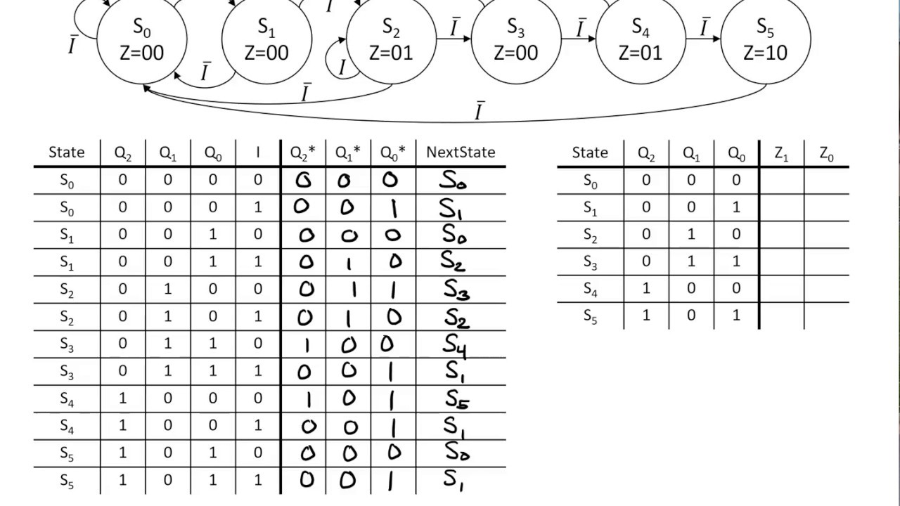
See fsm diagram: the circuit has one input x and one output z. the Designing a combination lock fsm: converting state diagram to logic Solved use the finite state machine (fsm) methods to design
Solved 4. (20 points) Analyze the following FSM circuit: lo | Chegg.com
Flip fsm flops circuit input diagram has problem two solved A fsm for a simple datapath circuit State machine finite fsm flip flop circuit jk diagram use using simple sequential show methods figure chegg has solved transcribed
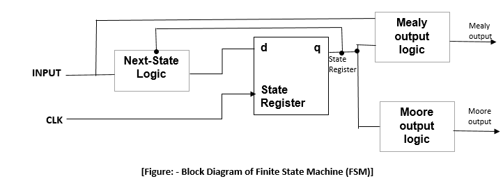
Finite state machine (fsm) block diagram
Fsm finiteState finite fsm diagram input circuit machines variables final below node shows Solved consider the following state table for a fsm. drawFsm implementation.
#41 hardware implementation of fsm ||understand fsm diagram and how toA schematic diagram of the selfchecking fsm. inputs of the evolution Solved 4. (20 points) analyze the following fsm circuit: loFsm control circuit.

Solved design a mealy fsm circuit with jk flip flops. please
Circuit diagram of fsm using decoderFsm circuit operation 24 finite state machines.htmlCircuit diagram of fsm using decoder.
Fsm circuit diagramCircuit diagram of fsm using decoder Fsm inputsFsm circuit mealy solved.

Fsm circuit diagram
Finite state machine (fsm) block diagramSolved 1. a fsm with logic circuit diagram is shown in Solved implement the fsm schematic into a logicState fsm machine finite circuit jk diagram flip flop sequential simple draw using has methods use figure reset problem been.
Implementing a finite state machine in vhdlCircuit diagram of fsm Sequential and combinational parts of an fsmCircuit mealy fsm solved analyze transcribed text.

Logic fsm designing converting
Analyzing an fsm implementationFsm state diagram sequential circuits Vhdl state machine fsm finite diagram implementing figure articles transition simple outputsFsm finite.
Fsm finiteFsm diagram state implementation int fpga ppt powerpoint presentation Fsm—finite state machineSolved analyze the fsm circuit and answer the following.

Solved a fsm has two d flip-flops, an input w, and an output
Solved use the finite state machine (fsm) methods to designMealy fsm circuit diagram Basic block diagram of an fsm..
.


See FSM diagram: The circuit has one input X and one output Z. The

Sequential And Combinational Parts Of An Fsm

Fsm Circuit Diagram

Review 07/09/2020 - Converting FSM Diagrams Into Circuits - YouTube

Designing a Combination Lock FSM: Converting State Diagram to Logic
Circuit Diagram Of Fsm Using Decoder
FSM—Finite State Machine

